
- Efficiently performs commonly used audio functions by using fixed-function hardware blocks: XMA, Sample Rate Convertor (SRC), equalizer and compression, and filter volume
- Provides a programmable, embedded Audio Control Processor (ACP) to control these blocks
- A Direct Memory Access (DMA) process for accessing system memory
- Special internal memory, called mix buffers A mix buffer is a block of memory that stores one full audio frame of data. SHAPE hardware typically reads from one or two mix buffers and writes to an output mix buffer. There are a few exceptions to this general process, such as XMA decoding and the DMA and SRC blocks.
XAudio2 and audio middleware implement SHAPE components implicitly. However, constructing flowgraphs provides the greatest flexibility and access to the audio-acceleration capabilities of the XBOX One console.
This topic provides an overview of the SHAPE hardware and the function blocks.
- Control flow
- DMA
- XMA
- PCM
- Sample Rate Convertor (SRC) block
- Equalization and compression
- Filter/volume block (FLTVOL)
- Mix buffers
- Overflow, magnitude, and saturation
- SHAPE queues
- Programming considerations
Control flow
The following is a typical control flow for audio processing.- A compressed XMA audio data file is loaded into main system memory.
- The XMA decoder block decodes a portion of the XMA data into Pulse Code Modulation (PCM) data. This stores the output in an XMA decode buffer in system memory.
- The SRC block reads the PCM samples from the XMA decode buffer and performs the necessary sample rate conversion and pitch shifting. This allows audio data of an arbitrary sampling rate to be brought into the SHAPE accelerator blocks. The SRC block outputs audio data that’s running at the fixed rate of 48 KHz to an internal mix buffer.
- Any additional SHAPE processing and the reading and writing to temporary mix buffers is now performed. The processing is controlled by the ACP, which itself is driven by the application through the ACP API that’s described in this documentation set. The processing includes equalization, compression, filter scaling, and volume scaling.
- The final stage, called Speaker Output Accumulation, is where speaker mix buffers collect and mix the samples from multiple sound sources for playback. Optional global audio effects can be processed at this stage.
- A compressed XMA audio data file is loaded into main system memory.
- The XMA decoder block decodes a portion of the XMA data into PCM data, storing the output in an XMA decode buffer in system memory.
- The SRC block reads the PCM samples from the XMA decode buffer and performs the necessary sample rate conversion and pitch shifting. This allows audio data of an arbitrary sampling rate to be brought into the SHAPE accelerator blocks. The SRC block outputs audio data that’s running at the fixed rate of 48 KHz to an internal mix buffer.
- At this step, the process flow diverges. The DMA system is used to transfer one or more mix buffers to main system memory.
- The application CPU performs any required signal processing on the buffer in main memory.
- The DMA system is used to transfer the processed audio data from the main memory buffer into a temporary mix buffer. After this step, the process is identical to that described previously.
- Any additional SHAPE processing and the reading and writing to temporary mix buffers is now performed. The processing is controlled by the ACP, which itself is driven by the application through the ACP API described in this documentation set. The processing includes equalization, compression, filter scaling, and volume scaling.
- The final stage, Speaker Output Accumulation, is where speaker mix buffers collect and mix the samples from multiple sound sources for playback. Optional global audio effects can be processed at this stage.
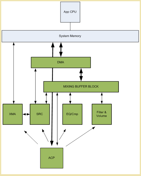
DMA
The Direct Memory Access (DMA) system supports read/write functionality with automatic conversion of float-to-integer and integer-to-float. The DMA system uses circular buffers that contain de-interleaved samples in 128-sample blocks. The DMA processor allows the SHAPE engine to send data from mix buffers to main system memory and to retrieve data from main system memory into the mix buffers, for further processing. DMA is performed per block. One audio frame of data is transferred at a time. To facilitate block-interleaved data, a skip value specifies the number of audio frame blocks in system memory that are to be skipped (from the base address) when samples are read or written. For this reason, multichannel streams require one DMA context per channel. Audio data samples are always read and written as 32-bit values, either as integers or floats, and as specified in the DMA contextFloatConvert flag. To help reduce the amount of data bandwidth, the direction of the DMA (read or write) is specified in the DMA command rather than in the DMA context. The DMA engine has no signal processing but can convert floats to integers and integers to floats. This allows the application CPU to process data samples in floating-point format.
To calculate the size of a DMA buffer, use the following formula.

XMA
The XMA format supports mono, stereo, and interleaved multichannel sound with variable bit rates and compression. Several improvements have been made over the XBOX 360 implementation of XMA, including an increase in the clock rate (with a 40 percent improvement in the pitch shifting capabilities, for example) and an increase in the voice count from 320 to 512. The XMA decoder block decodes a portion of the XMA data in main memory and returns the PCM data to an XMA decode buffer in main memory. The XMA decoder block is identical to the XBOX 360 XMA decoder block except for minor, state-related enhancements for interfacing with other SHAPE components. The XMA decoder register block has been augmented with the state information that’s related to the decoded output for each voice. Five bits per XMA context specify the amount of audio data that remains unconsumed in the PCM output buffer. These registers are implemented inside the XMA decoder block. This always makes them available for determining whether there are enough samples to lock the context for the SRC without reading main memory.xWMA is not supported by SHAPE but is supported by using
XAudio2.PCM
Linear Pulse Code Modulation (PCM) supports up to 7.1 surround sound at 48 KHz. The ACP will downmix if the sound system of the user is, for example, 5.1 surround sound or stereo. S/PDIF output will be supported. Support is also available for linear and circular PCM buffers that contain 16-bit mono or stereo integers, 32-bit mono floats, or 32-bit mono integers (24 bits left justified, or 32 bits with the lower 8 bits masked off).Sample Rate Convertor (SRC) block
The SRC block performs integer-based sample rate conversion and writes the output data to the mix buffers. SRC is typically used for emulation of musical instruments, conversion of input samples to an octave lower or higher than that of the source, and for Doppler and other effects. From system memory, the SRC block reads either 32-bit floating-point PCM data or the 16-bit, 24-bit, or 32-bit fixed-point data. For input data, the block can take either the output of the XMA hardware decoder or the data maintained by software. Because it’s tightly integrated with the XMA decoder, the SRC block can determine whether the number of samples of decoded PCM data in the XMA decode buffer is sufficient for creating and completing an audio frame of samples without reading main memory. SRC operates in mono or stereo mode. The PCM data is read from memory and converted to a common 24-bit, fixed-point format for sample rate conversion. The output is written to either one or two mix buffers, depending on the mode. Stereo data is stored in memory as an interleaved stream of 16-bit data. The left channel is in the least significant 16 bits of each 32-bit word, and the right channel is in the most significant 16 bits. Also in stereo mode, the PCM data is read and simultaneously de-interleaved. The left channel data (sample 0,2,4,6…) is processed and output to one mix buffer. The right channel data (sample 1,3,5,7…) is written to a second mix buffer. Figure 3 shows sample rate conversion modes. Figure 3. Sample rate conversion modes.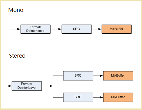
Equalization and compression
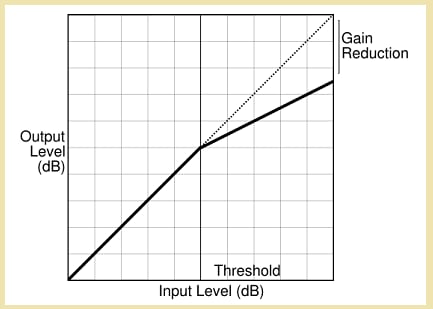
The compressor limits the dynamic range of the signal by monitoring the level of input and creating a dynamic gain value. The compressor then uses the gain value as a multiplier of the signal, scaling it appropriately, according to the current level of the input signal. In other words, the compressor is an automatic volume control that’s constantly monitoring the input signal and adjusting itself. The compressor acts only on signals that exceed a specific threshold. Signals under the threshold pass through unaltered. Threshold is set by the application as part of the EQComp context data. A programmable control in the context is used to perform compression or expansion. The compressor alters the sound data according to a parameter that specifies the ratio of incoming level to outgoing level. The ratio represents the extent of attenuation to be performed on the incoming signal if it exceeds the threshold. Examples are as follows.- At 2:1, for every 2 dB over the threshold, the compressor outputs 1 dB over the threshold level.
- At 1:1, the compressor is essentially off.
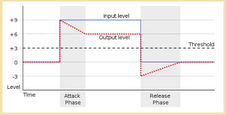
attack and release parameters specify how quickly the compressor is activated; that is, how long does it take to fully attenuate, by the amount specified by the ratio, the sounds that exceed the threshold. Attack and release are specified in milliseconds and correspond to how quickly the compressor is to vary the output gain in response to a signal that exceeds the threshold or falls below it. These adjustments can be linear or log based.
The following diagram (figure 5) shows how the output level you want isn’t achieved until the input has exceeded the threshold for the time specified by attack. The diagram also shows how the input and output return to unity only after the input is under the threshold for the time specified by release.
Figure 5. The attack/release timing.
RMS. In normal mode, the input level is instantaneous and calculated for every sample. In RMS mode, a running average (an approximation of the RMS value) is kept over the previous 128 samples. The running average is used as the input level rather than the absolute level of the current input sample.
The EQ/Compressor-Expander block contains two separate processing units in series: a three-band programmable equalizer and a dynamic-range compressor (figure 6). The block is used to control the frequency and dynamic range of sounds, and it takes input from one or two mix buffers.
- One input is the audio signal to be processed.
- The second input, called sidechain, is the optional control signal used to determine the audio compression.

-
In Normal mode (figure 7), there’s a single audio input from a mix buffer. The input is fed through the equalizer where it’s subsequently processed by the compressor and output to a mix buffer.
Figure 7. Normal mode.

-
In Internal mode (figure 8), the input signal is fed directly into the audio input of the compressor, and it’s split and sent to the equalizer. From the equalizer, it’s sent to the sidechain input of the compressor.
Figure 8. Internal mode.

-
In External mode (figure 9), two separate input signals are used from two separate mix buffers. The input signal is fed through the equalizer and into the audio input of the compression block. The sidechain input signal is fed directly into the sidechain input of the compressor.
Figure 9. External mode.

Filter/volume block (FLTVOL)
FLTVOL is used to do the following:- Model the occlusion of sounds going around or through an object
- Distribute the energy of sound to multiple speakers, to model the direction in which sound arrives.
f and q parameters are calculated by software outside the SHAPE block. When a coefficient is updated, it’s ramped to the new value over the course of one audio frame. Control bits are used to determine which output (band reject, High-pass, Band-pass, or Low-pass) is to be used as the final output of the FLTVOL block.
The context data for each channel or stream is stored in system memory. Though performance is limited to 2560 48-KHz simultaneous streams (which means SHAPE can process up to 2560 FLTVOL contexts per audio frame), the number of contexts addressable in memory is larger, to simplify the scenarios of stream reuse.
The filtering behavior is designed to be identical to that of XAudio2.
Mix buffers
Mix buffers serve three main purposes.- Mix buffers act as a final mixing destination for each speaker output for the system (or an individual player). When each sound is processed, its subsequent output is mixed into these buffers.
- Mix buffers act as temporary storage locations when buffers of audio data are passed between hardware blocks.
- In conjunction with the DMA engine, mix buffers serve as a mechanism for passing data from the SHAPE hardware and audio subsystem up to the main system as well as for passing data from main system memory back to the SHAPE hardware and audio subsystem.
Overflow, magnitude, and saturation
In a title audio engine, managing headroom can be very difficult. For this reason, each SHAPE block maintains the state associated with signal overhead and gain. Each block other than SRC maintains a flag that indicates if internal saturation has occurred during processing. In addition to the internal saturation flag, each hardware block also maintains two four-bit numbers that represent the magnitude of the output of the hardware block. The magnitude is calculated by determining the peak output during the audio frame and by counting the leading zeros of the absolute value of the peak. One four-bit number is maintained with the persistent peak magnitude, and the other is reset by the hardware for every audio frame. In addition to monitoring the peak magnitude of each individual hardware block, the peak magnitude of the mix buffers is also maintained. When the output of a hardware block is added to a mix buffer, the peak magnitude is calculated in the same manner - by counting the leading zeros. Each hardware block state maintains an additional pair of four-bit peak magnitude values. These values represent the peak magnitude of the mix buffer after the output of the hardware block has been accumulated into the mix buffer. One four-bit number represents the ongoing, persistent peak magnitude. The other is updated for every audio frame. The peak magnitude values are saved in the context of the SHAPE blocks, even though what’s being represented is the mix buffer state. Peak magnitude is encoded according to the following table (coded in the ShapeHardwareContexts.h file).
To help manage overhead and to avoid overflow and saturation, in addition to fine-grained gain settings, a 0-to-7-bit right shift may be performed on the output of a hardware block prior to the accumulation into the output mix buffer. This is designated in the context of each SHAPE hardware block.
SHAPE queues
The SHAPE audio processor manages two queues that help reduce system hardware and app hardware interlocks.- The Command and Control Queue (CCQ) is used to give the SHAPE audio processor a series of commands to execute whenever it can - usually when it completes the processing of the current audio frame. The SHAPE Execution List is read once for every audio frame output. However, the CCQ will be read and executed only once. The CCQ is the mechanism for having the CPU update any block context data on an audio frame boundary without requiring a hardware interlock with the SHAPE hardware. Examples of this include supplying more bit-stream data for the XMA block, updating context parameters for various blocks, and pointing to a new execution list. This is usually done while the audio processing flowgraph is changed.
- The Status and Reporting Queue (SRQ) is used by the SHAPE audio processor to report to the CPU various events that don’t require real-time responses. Examples include updating of bit-stream buffer consumption, errors, warnings and flags, debug data, performance data, and status information.
Programming considerations
Programming directly to the SHAPE hardware is enabled through theIACPHAL interface. However, the process of preparing audio data for the SHAPE hardware is complex. Many utility methods, structures, and enumerations are provided. These utilities provide all or most of the methods that are needed to control the SHAPE hardware. The Microsoft Game Development Kit (GDK) includes source code for these utilities for the rare cases where amending the code is necessary to handle certain kinds of data.
The only header file to be explicitly included in your project is acphal.h, which references all utility header files. All utility functions reference the NO_SHAPE_CONTEXT_VALIDATION macro. If this macro is defined, all validations will be omitted. This will be useful for final retail builds.
For more details about sharing SHAPE and XMA resources with instances of XAudio2, see the Remarks section of the XAudio2Create function.
For more details about all utility methods, see ACP overview.
Persistent and non-persistent flowgraphs
You can submit flowgraphs to be processed as persistent or non-persistent. Persistent flowgraphs are processed and remain resident so that their processing is repeated in the next frame after the read and write pointers have advanced and after other context information is updated. Use persistent flowgraphs for either of the following scenarios.- Highly complex flowgraphs, which require a significant amount of CPU processing to reassemble each frame
- Highly static flowgraphs, which have the same number and configuration of voices for an extended period
- Voice topologies are changing frequently.
- The processing cadence of your title’s audio software engine is detached from the SHAPE hardware; that is, it’s not a multiple of 2.667 MS.
- You want to run audio processing faster than real time, where you submit graphs to be consumed as quickly as they are available.
Debugging issues
When you develop flowgraphs, registering for messages will help debug any issues that might occur. Specifically, use theNumMessages parameter of Connect. The messaging system provides rich feedback on a variety of issues, including invalid flowgraphs (ACP_FLOWGRAPH_TERMINATED_REASON_INVALID_GRAPH), blocked commands, and frame-outs caused when you attempt to perform more processing than the hardware’s frame size of 2.667 MS allows. Before shipping a title, verify that flowgraph processing is consistently successful by observing the ACP_MESSAGE_TYPE_FLOWGRAPH_COMPLETED messages for each submitted flowgraph.
Missed messages
If you use ACP messages to drive the engine state, and if you handle many messages, you should examine thedroppedMessageCount field of ACP_MESSAGE during development. A non-zero value of the field indicates that the message queue was full and messages had to be dropped. In this scenario, consider servicing the queue faster and making it larger.
Frame-outs
There are many reasons a flowgraph might not be completed before the end of an audio frame (2.667 MS) is encountered, for example, processing of too many flowgraphs or processing of a badly structured flowgraph. This incomplete flowgraph will result in anACP_FLOWGRAPH_TERMINATED_TIME_EXCEEDED message for persistent flowgraphs, and these persistent flowgraphs will be incomplete. By contrast, a non-persistent flowgraph isn’t constrained in this way and will run until it’s completed, even across frames.
Blocked commands
SRC and DMA commands might get reported as blocked (ACP_MESSAGE_TYPE_SRC_BLOCKED, ACP_MESSAGE_TYPE_DMA_BLOCKED) in several scenarios as shown in the following table.
| Command type| Blocking scenario|
| --- | --- | --- | --- |
| XMA SRC| The associated XMA context has a parser error or no source data. The error is SHAPE_XMA_ERROR_STATUS_READ_BUFFER_INVALID_VALIDBUFFER_CURRBUF_IS_0 | SHAPE_XMA_ERROR_STATUS_FRAME_CROSSES_BOUNDARY_INTO_INVALID_READ_BUFFER_VALIDBUFFER_CURRBUF_IS_0 | SHAPE_XMA_ERROR_STATUS_FRAME_CROSSES_BOTH_READ_BUFFER_BOUNDARIES. XMA SRC won’t block based on a lack of decoded data.|
| PCM SRC| Associated PCM context is SHAPE_PCM_MODE_CIRCULAR, and there is no source data.|
| Read (DMA from mix buffer)| DMA buffer is full.|
| Write (DMA to mix buffer)| DMA buffer is empty.|
After commands are determined to be blocked (which occurs both before they are added to a SHAPE queue for processing, and at runtime), they are removed from the graph, which might lead to dropped audio. During development, use blocked commands as the first place to look for improvements in the handling of flowgraphs. Also, before shipping, make sure that your title prevents commands from being blocked at all.
You can prevent the blocking of DMA commands by ensuring that your audio buffer is sufficiently large and that data is streamed at regular intervals in relation to the buffer size. For example, if you’re streaming four hardware frames at a time, ensure some multiple of those frames (at least double-buffered at eight) are in the buffer so that the hardware can write ahead of the read pointer of the title. Alternatively, you could enforce emptying of the buffer before submitting the next flowgraph: consume, update the DMA read pointer, and then submit the flowgraph.
SRC commands have three modes.
SHAPE_SRC_COMMAND_TYPE_STARTis used for nearly all SRC commands in a flowgraph. Perform normal processing and expect more audio data to follow the current flowgraph.SHAPE_SRC_COMMAND_TYPE_STOP_IMMEDIATEis used to immediately stop processing the source XMA or PCM data. The SRC will output a zeroed buffer for this frame.SHAPE_SRC_COMMAND_TYPE_STOP_ENDis used to indicate the last packet of a voice.
STOP_END or STOP_IMMEDIATE, the SRC command won’t be completed, which will cause the active flowgraph to stall. A persistent flowgraph will terminate at the end of the audio frame, and a non-persistent flowgraph will never be completed.
Synchronization issues
Synchronization issues might arise if you don’t respect the SHAPE hardware’s consumption practices for contexts and commands. While your titles retain full access to ACP-allocated memory, take care not to modify a context structure while it’s in use. You can use SubmitCommand to submit commands to occur at a specific frame, at the beginning of the next frame, or as soon as possible.The “as soon as possible” scenario is still asynchronous from any title CPU processing. Some commands might not be completed immediately, such as if a context is in the middle of a non-interruptible operation. Wait for an
ACP_MESSAGE_TYPE_COMMAND_COMPLETED to verify that a command has been truly processed.